FC Data Analysis and Graphing
Microbiology 542
All software needed for your FC data analysis is free, and the software and data can be downloaded from the web. You may do all or part of this assignment on your home computer, or any Windows 95/98/NT4 computer. (The software is available only for Windows; it won't run on Macintosh.)

The instructions below assume that WinMDI and PrintKey are already installed. If not, here are instructions.

WinMDI Setup

  1. Open Netscape, go to http://www.bio.umass.edu/immunology/5flowcyt.html. Find the "Raw data" section, and select the key to data files for the current year, then write down the file number for your sample(s). Files are named 542YYNNN.bin, where YY is the year, and NNN is the file number. So for file number 44 in year 2003, the filename will be 54203044.bin.
  2. Open Windows Explorer. If it is not available from the desktop, use the Start menu, select Programs, and open Windows Explorer.
  3. Using Windows Explorer, create a working folder (directory) in which to store your raw data, and the graphs and html files you will save.
  4. In Netscape, under "Raw data", click on the link for "splenocytes & thymocytes" for the current year. Download your data file(s), saving them into your working folder.
  5. Printkey should be running. When Printkey is first run, nothing happens except that a new icon (white hand pressing key) will appear in the taskbar icon tray (at the lower right of your screen). You'll use PrintKey when saving screen images (see box below). Press the PrtSc (PrintScreen) key on your keyboard, and PrintKey's window will appear after a brief delay. Use PrintKey's Options menu to check "Get only client area of window". Open the Options menu again to be sure this option is checked. Then close PrintKey's window (click on the X in the upper right corner).
  6. Run WinMDI. Select dot plot, and open one of your data files, and click OK (accepting the default dot plot: forward scatter vs. side scatter).
  7. Size your WinMDI window to about 3/4 of the width of your screen (but close to full height). This will help to keep the graphics you will save narrow enough to view comfortably in a web browser.
  8. Select WinMDI's File menu, then Preferences. Select the following:
  9. Click on the dotplot to open its menu. Select Format. In the "Format Dotplot" dialog, select "All" under "Plot number of events". Under "Draw option" check "Color 2D Regions". Then click OK. Your dotplot should now look approximately similar to one of these. (Results may vary from year to year; the figures below are for 1997.)

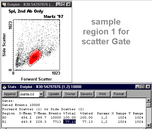
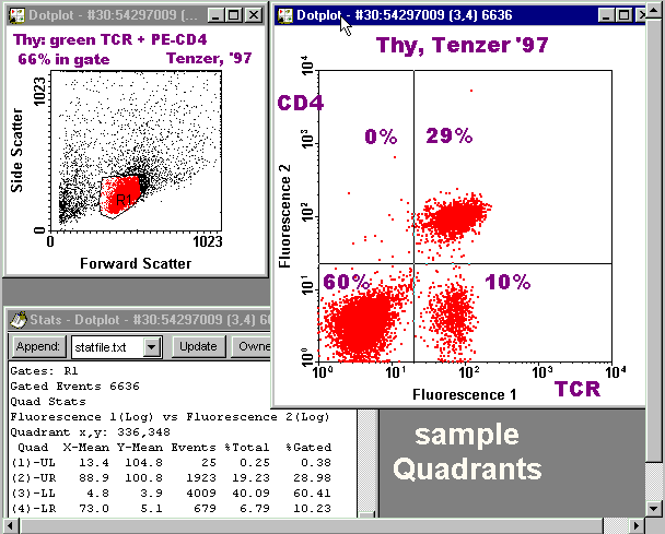
  10. Scatter Gate Dotplot with Stats
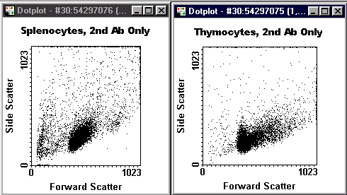

  11. Create Region 1 (for your scatter gate). Click in your dot plot and from the menu which pops up, select Regions. Push the Create button. Draw your scatter gate polygon (click for each vertex), close it, and press OK. See scatter gate examples below.
  12. Select Stats on the pop-up menu. In the Stats window, press the [Format] button and UNcheck: Sample ID, Geometric log means, Peak Channel Value, Use tabbed format. (Everything else should be checked.)
  13. Use the menu to Annotate your scatter plot with:
  14. Use the [Select new font] button to select an appropriate font and size, for example Arial Black, Regular, Size 10.
  15. Resize/reposition your dot plot and your stats window so you can see both. If you have less than 50% of events in your gate, check with a TA. Your window should look similar to the example below. See scatter gate examples below. Have a TA check your window before you save it.
  16. Save a snapshot (GIF file) of your graphic (see box below), naming it yynnng.gif
  17. Saving a screen image to GIF disk file.
    1. Saving a snapshot of your WinMDI image is "handing it in" for grading. Once you close WinMDI, you can't change a saved image (unless you start over)! (Before closing WinMDI, you can re-save the image after making changes.) Before saving, verify:
      1. (Omit this step for your gate snapshot -- for the gate file the 'gate' should not be turned on and all 10000 events should be shown, both red and black dots.) Proper scatter gate must be on. If the gate is on, the events must be less than 10000!
      2. Disk filename is visible for confirmation at the top of each graph and inside the Stats window. 
      3. Lowest applicable row in Stats table is visible. 
      4. Both axes are labeled with specifity names in each graph. 
      5. At the top of each graph should be the cell type, your last name (or the person who made the sample), and the current year (or year sample was made). When multiple histograms are overlayed in the same graph, there should be a color-matched list giving this information for each histogram.
      6. Annotation font is Arial Black size 10pt or a similar bold font easy to read from a distance (as when the image is projected).
    2. Hold down the Alt key, then press the PrtSc (PrintScreen) key. After a brief delay, PrintKey's window should appear. Verify that the correct image is in PrintKey's window. 

    3. (If the window doesn't appear or an earlier image is in it, close it. Use the taskbar to bring the PrintKey window to the front, close the PrintKey window, and press Alt-PrtSc again.)
    4. Use PrintKey's File menu, selecting Save the picture (or press the Save icon). All filenames must have this format: yynnnt.gif as follows: 
      • yy = last two digits of the Year
      • nnn = THREE (3) digits of your sample file Number (use leading zeros to make 3 digits)
      • t = one letter for graph Type (g for gate, h for histograms, o for overlayed histograms, q for quadrants)
      • .gif = all files must end in ".gif" to signal their type (GIF = Graphics Interchange Format) to web servers and browsers. 
    For example, if your sample number is 044, the year is 2003, and you are saving your first histogram image, your filename should be 03044h.gif. Save the GIF file into your working folder
      If you have more than one image of a particular type (for example a second version of your histograms) you can add a number after the type letter (for example 03044h2.gif).
  18. Wait till the message box "Picture Successfully Saved as .GIF" appears, and press OK, and close PrintKey. (If you don't close it, it won't save your next image until you do close it.) 
  19. Important: View your image in Netscape to verify that it was saved correctly. In Netscape's File, Open Page dialog, point to your newly saved GIF file and open it. Your image should appear on Netscape's "paper". 
  20. It would be good to copy this GIF file now to your diskette, ready to hand in. This will also give you two copies, in case you accidentally overwrite one of them.
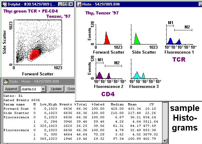
  21. Gated Histograms with Markers and Stats


  22. In WinMDI, keep the scatter dot plot showing your gate, but close the Stats window.
  23. Pull down the Display menu and select Histogram. Select your file. Press Read (accepting Show all parameters). (Pull out the lower right corner of the histogram window till the histograms look good.) No stains used in this experiment are reported in the Fluorescence 3 channel; it can be ignored.
  24. Notice the shapes of your histograms. Click on the histograms to pop up the menu, select Gates, and set R1 (or the appropriate region) to 'And'. Press OK. Notice the changes in the histograms.
  25. If you have multiple peaks, select Markers from the menu. On the "Set marker tool" dialog, choose a parameter with multiple peaks. Right-click to set the high end of the marker spanning the low-intensity peak (the low end will default to the bottom of the scale). Change the Marker Index to 2. Left click to set the low end of of the marker spanning the high-intensity peak. (If there is a third peak, use Marker Index 3.) No two markers should overlap.
  26. If you have multiple peaks in other parameters, repeat the previous step for each such parameter.
  27. Annotate. Put your name and the year at the top. Annotate the abcissa of the FL1 and FL2 histograms with the specifities (if any).
  28. Open the Stats window.
  29. Position and size your windows so everything essential is visible. It should look similar to the example below.
  30. See histogram examples below. Have a TA check your graphic.
  31. Save your image to a GIF file, yynnnh.gif
  32. The figure at the right illustrates the relationships between histograms for FL1 and FL2 and a two-color dotplot.

    Notice that the second peak in the FL1 histogram, and the first peak in the FL2 histogram, each contain two subpopulations which are resolved in the dotplot. The existence of the cloud in the lower right quadrant cannot be appreciated from either histogram.

    This figure is for illustration only -- you are not required to make one such as this.

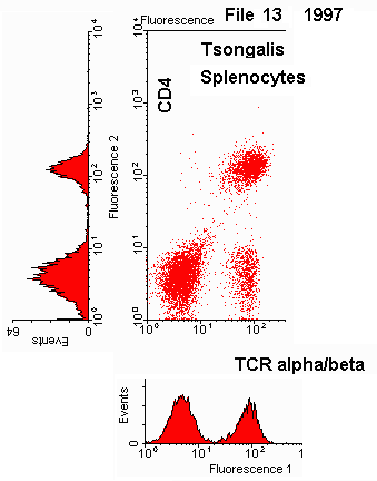
    Gated Two-Color Quadrant DotPlot with Stats

  33. In WinMDI, keep the scatter dot plot showing your gate, but close the Stats window and minimize the Histograms window.
  34. If none of your samples were stained with two colors of fluorescence, then this section does not apply, and you can go on to the next section. (Optionally, you may wish to make a quadrant graph using a classmate's data file. However, in this case, don't hand in a GIF file.)
  35. Use the Display menu to open your file in a dot plot, selecting Fluorescence 1 and Fluorescence 2 as X and Y on the plot. (If you forget to select FL1 and FL2 before the dot plot appears, you can do it by clicking on the dot plot and selecting Format.)
  36. Use the dotplot menu to select Format, and check "Color 2D regions", OK. This should result in both red dots (in R1) and black dots (outside of R1).
  37. Turn on the appropriate gate. (Dots should now be only red.)
  38. Use the pop-up Quadrants menu, hold down the left mouse button, and drag the center of the quadrants to the position which best separates your dot clouds.
  39. Open the Stats window.
  40. Annotate your quadrant plot as shown in the example below. In the example all annotations are purple, but you can leave your annotations black.
  41. See quadrant examples below. Have a TA check your graphic.
  42. Save your image to a GIF file named yynnnq.gif
  43. Corrected Fluorescence Intensities (CFI)

  44. Returning to www.bio.umass.edu/immunology/5flowcyt.html, click on the link to "Report Form: Corrected Fluorescence Intensities from Histograms".
  45. With the form displayed in the browser, use Netscape's File menu to select Edit Page. The top (blue) bar should now say "Netscape Composer".
  46. Use Netscape's File menu and select Save as. Specify a filename of the form yynnncfi.htm (for example 01023cfi.htm) and save to your working folder. (Accept the default page title, same as the filename.)
  47. Using the intensities on the stats of your histograms graphic, fill in the form in Netscape Composer. Get the control values for the current year on the Flow Cytometry Resources page at the class website (www.bio.umass.edu/immunology/5flowcyt.html), under Results, Control Fluorescence Intensities. These values go in the Control (Blank) section of your form.
  48. Have your Corrected Fluorescence Intensities form checked by an instructor.
  49. Save the changes to your form to the .htm file in your working folder (File, Save).

  50. If you did more than one sample, repeat the above steps for each, making GIF files for a scatter Gate, Histograms, two-color Quadrants (if appropriate), and a CFI Form.
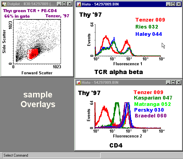
  51. Gated Overlayed Histograms

    Making overlayed histograms involves comparing your results with results of your classmates. It should not be started until you have completed the Gates, Histograms, Quadrants, and CFI Forms for your files. Making overlayed histograms is especially important for any sample which has only one color of fluorescence, but can also be very useful for two-color samples (one color at a time).

  52. Choose another sample (probably by a classmate, or possibly from a previous year) which will make a histogram with the same fluorescence color as your sample, and one worth comparing as an overlay. Examples could be: the same antibody on the same cells, the same antibody on the other cell type, or a different antibody (of the same color) on the same cells.
  53. Minimize all windows except your scatter dot plot window showing R1.
  54. Display, Histogram, but select a single parameter, and open out the histogram window.
  55. Click on the histogram and use the Format dialog to UNcheck "Solid fill". Increase the line width to medium thickness, and increase "Smooth" from 0 to 10.
  56. In the format dialog, press [New file], and select the file to be compared. On the "Select parameters" dialog, press [Gates] and activate the appropriate region (which may be different if the cell type is different!). IMPORTANT: instead of pressing the [Read] button, press the [Overlay] button.
  57. In the format dialog, select the new file in the "Overlays" section, then increase the line thickness to medium and change the color if needed to contrast with the other histogram.
  58. Annotate in matching colors following the example below.
  59. Overlay additional histograms as appropriate.
  60. Save a GIF file, naming it yynnno.gif

  61. Before Leaving the Computer Lab

  62. Copy all your .gif files and your .htm files from your working folder to a diskette. Hand in a diskette with completed files to an instructor. Don't count on your files still being on this computer at the next class! Whether you copy your FC data files is optional since they can always be obtained from the web.